Before beginning, I should note that this book makes the assumption that the vehicle you own has a 12-volt negative ground charging sys-tem. That is, the vehicle is equipped with a 12-volt battery and its negative terminal is connected to the vehicle chassis. If you own a vehicle with a 6-volt or even a positive-ground charging system, the theory still applies but the specifics do not.
The objective of this chapter is to provide a foundation for the rest of the book. Everything you need to know is explained so that you have a firm understanding of basic automotive electronics. Every other chapter in this book is written on the assumption that you’ve read and understand this one.
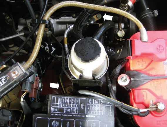
A standard 12-volt negative ground application always has the battery negative connected to the vehicle chassis and engine block. Note that in this 2004 Nissan Frontier, a single cable does double duty.
High Current/Low Voltage
The single most important thing to keep in mind when working on a vehicle’s electrical system is safety. Unlike the electrical system of your home, automotive electrical systems are low voltage, so there is little if any danger from shock. In addition, an automotive electrical system can deliver incredibly high currents—far in excess of the 15 amps available at a typical outlet in your living room. Finally, this current is direct current or DC versus the alternating current or AC found in your home.
- Automotive Electrical—Low Voltage/High Current (DC)
- Residential Electrical—High Voltage/Low Current (AC)
I assume that if you’re reading this book, then you’ve experienced first hand the results of a short circuit in an automobile. They can cause extreme damage quite quickly!
Now I know I promised this book won’t read like college-level physics, but I need to address two laws right away. A good friend once told me, “They’re laws, not just really good ideas.” Well put. The two laws that are paramount to understand for automotive wiring projects and nearly all electrical projects are Ohm’s Law and Kirchhoff’s Law.
Ohm’s Law
Ohm’s Law is generally considered the foundation of electronics. Named after the person that first defined it, Georg Ohm, Ohm’s Law simply states the relationship between voltage (E), current (I), and resistance (R).
Voltage- Difference in potential
- Measured in volts
- Typically expressed as E in mathematical formula
- Flow of electrons
- Measured in amperes (can be abbreviated as amps)
- Typically expressed as I in mathematical formula
- Opposition to the flow of electron
- Measured in ohms (interchangeable with the Ω symbol)
- Typically expressed as R in mathematical formula
This Tech Tip is From the Full Book, AUTOMOTIVE WIRING AND ELECTRICAL SYSTEMS. For a comprehensive guide on this entire subject you can visit this link:
LEARN MORE ABOUT THIS BOOK HERE
SHARE THIS ARTICLE: Please feel free to share this post on Facebook Groups or Forums/Blogs you read. You can use the social sharing buttons to the left, or copy and paste the website link http://www.cartechbooks.com/techtips/electrical-principles-and-simple-circuits/
Voltage is that which causes current to flow. Resistance is anything that impedes the flow of current. The higher the resistance, the higher the voltage required to allow a given amount of current to flow. This relationship between voltage, current, and resistance is expressed as:
I = E / R
If you know any two of the above, you can solve for the third. Using a little algebra, you can rearrange this formula to get the following formulas to aid in solving for the unknown:
E = I x R
R = E / I
Fortunately, the voltage available in a vehicle is somewhat fixed and typically is 12—12.6 VDC with the vehicle off and 13.0—14.4 VDC with the vehicle running.

Figure 1-1: This is Ohm’s Law pie chart. Simply cover the variable you wish to solve and it shows you the correct formula to do so. For example, to solve for I, cover the I, and the resulting formula is E/R.
Now that you know Ohm’s Law, let’s put it to work to determine how much resistance an electronic fuel pump has if it requires 10 amps of current at 12 Volts.
R = E / I
R = 12 volts / 10 amps
R = 1.2 Ω
The Power Formula
The Power Formula simply states the relationship between power, current and voltage. Power is an expression of work and is expressed in watts. Power is the product of cu0072rent and voltage and the relationship is expressed as:
P = I x E
Again, if you know any two, you can solve for the third. Once again, let’s use a little algebra to rearrange this formula to aid in solving for the unknown:
I = P / E
E = P / I

Figure 1-2: This is the Power Formula pie chart. As with the Ohm’s Law pie chart, simply covering the variable you wish to solve for shows you the correct formula to do so.
Now that you know the Power Formula, let’s use it to determine how much power the electronic fuel pump I spoke of above consumes:
P = I x E
P = 10 amps x 12 volts
P = 120 watts
An easy way to put the idea of power into perspective is to understand the simple incandescent light bulb. For example, a bulb rated 60 watts consumes 60 watts of power to light the filament within the bulb. Not all of the power across the filament can be converted to light—some of the 60 watts the bulb consumes is converted to heat. This is why the bulb gets hot in use. The same applies to electronic circuits in all automobiles.
In a simple circuit, a certain amount of power is dissipated across the load. The remaining power is dissipated into heat in the wiring, switch(es), and connections. By minimizing the amount of power burned up into heat, we can get more power to the load.
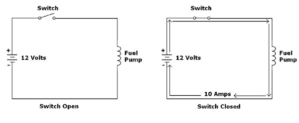
Figure 1-3: This is a simple electronic fuel pump circuit. Note that the circuits are the same, but the one on the left has the switch in the open position. No current can flow through the fuel pump until the switch is closed, as shown on the right.
Combinations
Many times, you need to solve problems that neither Ohm’s Law or The Power Formula addresses directly. However, they can provide the solution when you combine them via substitution. For example:
P= E2 / R
This formula would allow us to solve for power if we know voltage and resistance, but not current. How did we determine this? Simple, Ohm’s Law tells us that I = E / R, so we can substitute E/R for I in the Power Formula:
P = I x E (Recall that I = E / R)
P = ( E / R ) x E
P = E2 / R
Likewise, we can solve for power if we know current and resistance but not voltage the same way:
P = I x E (Recall that E = I x R)
P = I x ( I x R )
P = I2 R
Kirchhoff’s Law
If you were to Google this, you’d find the full explanation (and formulae)—quite a mouthful! Fortunately, this book sticks to what applies here. To explain Kirchhoff’s Law, I’ll separate it into the two different parts—one applies to voltage and the other to current.
Kirchhoff’s Voltage Law
Kirchhoff’s Voltage Law states that the sum of the voltages applied in a given circuit are equal to the sum of the voltage drops across the various components in said circuit. Figure 1-5 is an example of a simple lighting circuit with voltage drops specified.
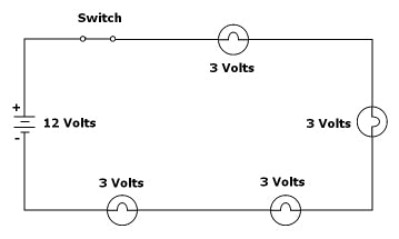
Figure 1-5: A simple lighting circuit illustrates Kirchhoff’s Voltage Law. Note that the sum of the voltages across each of the lights is the same as the total voltage applied to them.
Kirchhoff’s Current Law
Kirchhoff’s Current Law states that the current entering a junction in a circuit is equal to the current leaving said junction. Figure 1-6 is an example of a different kind of lighting circuit with current flow specified. (Note that this is a different kind of circuit than Figure 1-5—more on that briefly.)
Recall from your junior high school physical science class when you learned that energy can neither be created nor destroyed. This is called the conservation of energy. Kirchhoff’s Law helps us to apply the conservation of energy to basic electronic circuits. In the example I gave above for the 60-watt bulb, it should be clear that the power the filament consumed was divided between light and heat—none was destroyed.
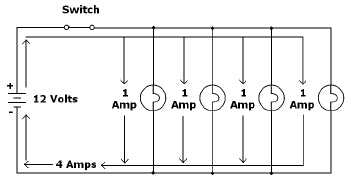
Figure 1-6: This simple lighting circuit helps explain Kirchhoff’s Current Law. Note that the sum of the currents through each of the lights is the same as the total current flowing through the circuit.
Understanding Ohm’s Law and Kirchhoff’s Law are paramount in grasping the basics of automotive electronics. Learn them and don’t forget them!
Circuit Basics
See, that wasn’t too bad! Now that you’ve gotten your Laws down, it’s important to understand the difference between the different types of circuits—specifically the series circuit, parallel circuit, and series-parallel circuit. Furthermore, it’s important to understand how Ohm’s Law and Kirchhoff’s Law govern these basic circuits.
Series Circuits
A series circuit is one that has all components connected in an end-to-end (or daisy chained) fashion. Operation of the circuit is dependent on all of the individual components of the circuit being in working order. A series circuit is only as good as its weakest link—if one component fails, so does the entire circuit. This is how strings of Christmas lights were once made. Problem was, when one bulb failed the entire string wouldn’t light.
In a series circuit, the following apply:
- The sum of voltages across the individual components is equal to the total voltage applied.
- The current flowing through the individual components is the same throughout the circuit. (Note the tie to Kirchhoff’s Law!)
Parallel Circuits
A parallel circuit is one that has all the components connected in a parallel fashion. Operation of the circuit is not dependant on the individual components of the circuit—one or more components could fail and the remaining components will still work. The typical parking light circuit is a good example of a parallel circuit.
In a parallel circuit, the following apply:
- The voltage flowing across the individual components is the same throughout the circuit.
- The sum of the currents across the individual components is equal to the total current flowing through the circuit.(Again, Kirchhoff’s Law.)
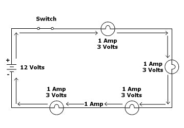
Figure 1-7: Series lighting circuit current specifications for all components. Note that this is the same circuit pictured in Figure 1-5.
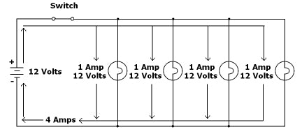
Figure 1-8: This shows you a simple parallel lighting circuit with voltage and current specified for all components. Note that this is the same circuit pictured in Figure 1-6.
Figures 1-7 and 1-8 illustrate the differences between these two circuits. Both are simple lighting circuits. Note that in both, I’ve outlined voltage and current across the various components as well as totals in the circuits so that you can see how Kirchhoff’s Law governs them.
Series-Parallel Circuits
You guessed it; there can be combinations of series and parallel circuits. These types of circuits, although not very common in automobiles, are referred to as series-parallel circuits. The rules above apply to the individual parts of the circuit. Figure 1-9 is an example of a series-parallel lighting circuit. Again, note how Kirchhoff’s Law governs this as well.
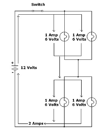
Figure 1-9: A series-parallel lighting circuit has voltage and current specified for all components. Note how Kirchhoff’s Law governs the Series part of the circuit and the Parallel part of the circuit differently.
It is important to understand the differences between series, parallel, and series-parallel circuits. Examples of each of them are found in nearly every vehicle on the road.
Short Circuit
For such a simple idea, this is one of the most misunderstood circuits that I know of. Quite simply, a short circuit is any circuit that has a circuit path between the battery (+) and battery (-). Certainly, these are not intentional and can be quite hazardous. Figure 1-10 shows a short circuit. Note that it is the same circuit as pictured in Figure 1-6, but the bulbs cannot illuminate as the circuit bypasses them.
How exactly does this happen? Any number of reasons. Let’s say that you were mounting something under the vehicle’s hood and you unintentionally pinched the parking light wire or pierced it with a screw in the process. All would be fine until you turned on the parking light switch, at which point, the parking light circuit fuse would blow as the switch just connected 12 volts directly to the vehicle’s chassis. The blown fuse just protected the wiring and vehicle from any serious damage. (The value of a fuse should be fairly clear at this point!) Of course, you would now have to determine what caused this and fix the problem. This process is called troubleshooting, and you’ll learn more about how to do this later in the book.
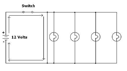
Figure 1-10: A short circuit, such as this, bypasses the lights altogether. Even though they are connected, they will not light.
This Tech Tip is From the Full Book, AUTOMOTIVE WIRING AND ELECTRICAL SYSTEMS. For a comprehensive guide on this entire subject you can visit this link:
LEARN MORE ABOUT THIS BOOK HERE
SHARE THIS ARTICLE: Please feel free to share this post on Facebook Groups or Forums/Blogs you read. You can use the social sharing buttons to the left, or copy and paste the website link http://www.cartechbooks.com/techtips/electrical-principles-and-simple-circuits/
Open Circuit
Now, this is the one that eludes folks—after all, any vehicle wiring problem is referred to as a short! In many cases, that just isn’t true. An open circuit is a break in the circuit that does not allow the circuit to operate. Recall the example I gave above in the series circuit explanation of the way strings of Christmas lights used to be manufactured. Should a bulb fail, and the string go out, this is an open circuit condition. Now, we don’t install many of these in vehicles, so let’s look at Figure 11—note that it is also based on Figure 6.

Figure 1-11: This open circuit is open in-between the two lights on the left and the two on the right. The two on the left work; the two on the right do not.
Again, there are any number of reasons for this to happen. Let’s say that you were installing new carpeting in your vehicle and you used a razor knife to cut an opening along the sill plate for the big Torx bolt that holds your seat belt down. If you’re not careful, you could cut through the wiring harness in this area, thereby removing the parking lights in the rear of the vehicle from the circuit. The front lights would still work fine because they are still connected to the circuit. Obviously, this is a simple fix, and it’s covered later in the book.
Wire Resistance Chart
We all know there is no such thing as a free lunch. Stranded copper wiring, which is what is typically specified for automotive use, has a certain amount of resistance per foot. This resistance per foot decreases as the gauge of wire increases (indicated by a smaller number; confusing, I know).
Figure 1-12 is the American Wire Gauge (AWG) standard for resistance of copper wire by the foot.
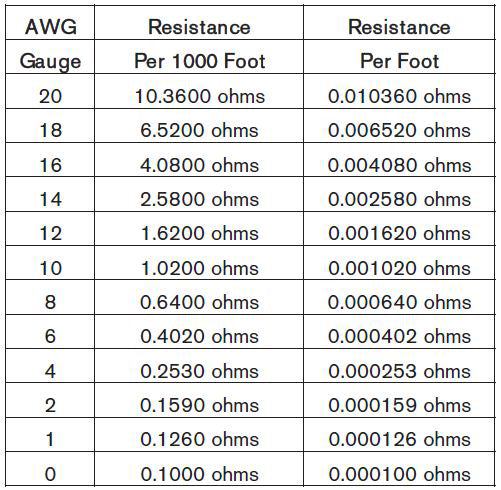
Figure 1-12: This chart outlines the resistance of stranded copper wire according to length and gauge. All gauges are according to the American Wire Gauge.
Example: Installing an Electric Fuel Pump
OK, now that you know your Laws and how they apply to basic circuits, it’s time to give you a real-world example. Let’s say that you just purchased an electric fuel pump and wanted to determine what gauge of wire to use to connect it.
Here’s what you should know:
- Current requirements of the pump at 12 VDC (this should be provided by the manufacturer). For the sake of this example, let’s say that it’s 10 amps.
- Length of wire from the ignition switch to the fuel pump—let’s assume this is 20 feet since it is typically located near the fuel tank.
- Length of return path from pump ground to charging system ground—let’s assume this is 5 feet (more on this later).
- Resistance of different gauges of wiring via the supplied AWG wire resistance chart.
We need to assume that the pump will only be running when the engine is running, so you should have 13.0 volts DC present at the ignition switch. For now, ignore the effect on available voltage other accessories will have. How do we determine this? Hint: Let’s put Ohms Law and Kirchhoff’s Law to work to solve this problem.
First, look at the circuit. Obviously, it’s a simple series circuit as shown in Figure 1-13.
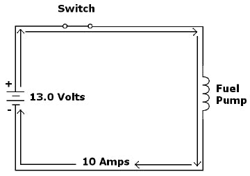
Figure 1-13: The sample electronic fuel pump circuit has a nominal voltage of 13.0 volts per the example.
Now refer to the AWG Wire Resistance Chart in Figure 1-10 to determine the resistance per foot of different gauges of stranded copper wire. Then use Ohm’s Law to deter mine how much voltage drop is incurred in our 25-foot run of wire with the 10-amp current requirements of our pump. Finally, use Kirchhoff’s Law to find out how much voltage is left to operate our fuel pump.
Let’s start with 18 gauge because this is exactly how the high-output fuel pump in my Oldsmobile was wired when I purchased it. The chart tells us that 18-gauge stranded copper wiring has .00652 Ω of resistance per foot. Use Ohm’s Law to calculate the voltage drop through the wiring:
E = I x R
E = 10 amps x (25 x .00652 Ω)
E = 10 amps x .163 Ω
E = 1.6 volts
Kirchhoff’s Law says that if you lose 1.6 volts in the wiring, you only have 11.4 volts across the pump itself as 13.0 volts – 1.6 volts = 11.4 volts. This voltage loss nets the voltage across the pump below the manufacturer’s specification of 12 volts. Not good! Especially for a fuel pump that needs to deliver the right amount of fuel to our engine at all times. We sure don’t want to ever run lean.
This voltage drop in the wiring is converted into heat, which causes the wire to be warm or even hot. See the sidebar “A Quick Exercise” for a further explanation.
Just by looking at the chart, you can guess that 16-gauge wire won’t cut it either. But, for argument’s sake, let’s do the calculation:
E = I x R
E = 10 amps x (25 x .00408 Ω)
E = 10 amps x (.102 Ω)
E = 1.02 volts
13.0 volts – 1.02 volts = 11.98 volts. With just over a volt lost in the wiring, the net voltage across the pump is again short of the manufacturer’s specification. This makes 16-gauge wire unsuitable for use.
Do the same math on 14-gauge wire:
E = I x R
E = 10 amps x (25 x .00258 Ω)
E = 10 amps x .0645 Ω
E = .65 volts
Do the same math on 12-gauge wire:
E = I x R
E = 10 amps x (25 x .00162 Ω)
E = 10 amps x .0405 Ω
E = .41 volts
13.0 volts – .41 volts = 12.59 volts. Better still, but now look at 10-gauge wire and see if the extra cost warrants its use:
E = I x R
E = 10 amps x (25 x .00102 Ω)
E = 10 amps x .02346 Ω
E = .26 volts
13.0 volts – .26 volts = 12.74 volts. This nets 12.74 volts across the pump, and it would continue to get closer to 13 Volts as you continue to increase the gauge of the wiring. However, you’re getting to the point of diminishing returns. The 14-gauge is the bare minimum, but for the cost difference I’d use 12-gauge or even 10-gauge to be confident the fuel pump is receiving ample current.
Keep in mind this example does not take into consideration the voltage drop through the fuse holder or connections. This voltage drop is due to their resistance and the resistance in the connections to them.
Chapter 3 shows you several methods to make strong, solid connections that minimize voltage drop through them.
Congratulations! You’re now versed in Ohm’s Law and Kirchhoff’s Law. In addition, you’ve learned the formulas and theory behind them to put them to work. You’ve also learned about basic types of automotive circuits. Finally, you’ve put all of this new information to work to solve real world problems. Now, how many of you intend to rewire that electronic fuel pump in your vehicle immediately after you get done reading this book?
I’m sure you’re eager to put your new knowledge to work. Half of the challenge in automotive electronics is understanding it. The other half is understanding how to apply what you know safely, which is addressed next.
Generally speaking, automobiles present a number of challenges when working on or adding to the electrical system. As I discussed earlier, extremely high currents are capable—anyone that has tightened a positive battery terminal with that shiny new long-handled ratchet can attest. In addition, accessing or routing wiring in many areas involves the ability to contort your body in the weirdest of positions.
More than a basic understanding and respect for the complexity of the electrical systems in today’s vehicles is required to work on them competently. The complexity of the modern vehicle is outside of the scope of this book. When in doubt, seek the advice of a professional—even if that means paying them to do the work. After all, this is how they make their living. Making simple mistakes on the modern vehicle can have serious and very expensive consequences; I cannot stress this enough!
Hazards Presented by On-Board Computers
Modern vehicles have many luxuries that we now take for granted, such as fuel injection, fully electronic automatic transmissions, anti-lock brakes (ABS), variable valve timing, supplemental restraint systems (SRS), and others. Each of these requires lots of decision-making power—power found in the host of on-board computers. The main vehicle computer is often referred to as the ECM (electronic control module), or PCM (powertrain control module).
Working on a vehicle with on-board computers is a way of life for today’s mechanics, and they’ve learned over the years that old school ways of troubleshooting problems are for old school vehicles. Case in point is the staple of many a mechanic’s tool box—the incandescent test light.
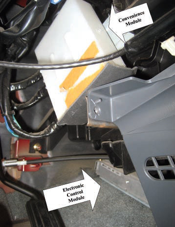
Two of the many modules and computers in the 2004 Nissan Frontier are shown: a convenience module, housing circuits that control the door locks, interior illumination circuits, etc; and the ECM. Both units are located above and to the right of the gas pedal and can be easily accessed.
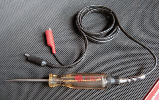
A Mac-computer-safe test light is radically different internally than a simple test light, although similar in appearance. The MAC Tools model ET125C is shown.
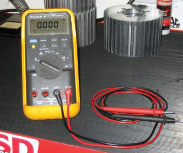
I bought my tried-and-true Fluke 87 in 1992, and it has served me well all these years. Although, it’s not an inexpensive meter, it’s loaded with many useful features.
The “test light” has very low resistance between its ground clip and probe tip—low enough to deploy an air bag in the event you’re probing around in the wrong area by accident. A better choice is a computer-safe test light. A digital multi-meter (DMM) is even better. The correct use of test lights and DMMs is covered in Chapter 2.
Another topic worth mentioning is that of connecting 12 volts or ground to any wire that you’re not 100 percent sure what it’s connected to. I sure wouldn’t do this in modern vehicles with electronic control units! Even the radio harness in today’s vehicles can include numerous connections to on-board computers, such as the vehicle speed sensing (VSS) circuit or a data connection to a vehicle locator for example. Don’t be a cowboy here! Only make connections to wiring you’ve verified. Fortunately, this is easy to do.
There are many sources on the Internet of wiring color codes and locations in vehicles. I can’t tell you how many times I’ve seen damage from somebody taking this info as gospel without verifying it. Connecting to the “brown wire in the driver-side kick panel” isn’t as easy as it sounds, especially if you look carefully and see that there might be numerous such wires in this area!
Finally, many of the connections between computers in the modern vehicle are of a new variety. Different BUS systems, such as CAN (controller area network) bus and MOST (media oriented systems transport) bus, are used in some vehicles. These BUS systems pass digital information to other components. Fiber optic cables are also becoming more common, and they also digitally pass information between components. Incidentally, we first saw widespread use of fiber optic cables in GM vehicles in the 1980s, and they were used for illumination.
Again, if in doubt, I recommend contacting a professional. It’s less expensive to swallow your pride than to pay for a costly mistake.
Disconnecting the Battery—When?
ADVISORY: When working on or servicing automotive batteries, it is advisable to wear eye protection. Many automotive batteries have sulfuric acid within them—this is extremely caustic and can cause irreversible damage to your eyes!
CAUTION: When working on or servicing automotive batteries, it is advisable to remove jewelry, such as rings and watches as they can be great conductors. If they accidentally come between the positive battery post or terminal and the vehicle chassis, they could cause a short circuit. This results in extremely high current flowing through them and this creates heat that can cause severe burns to your fingers, hand, or wrist!
CAUTION: Never work on or around an automotive battery with a lit cigarette! In addition, be very conscious of the proximity of open flames near or around the battery, as they can cause a lead acid battery to explode!
I’ve always been perplexed when the first line in the instructions of any aftermarket product begins with “Step 1: Disconnect the Battery.” Fact of the matter is, in many cases, this isn’t necessary nor advisable. Now, I’m not suggesting that you not follow the manufacturer’s instructions, but you should understand when to do this and when not to do this. Quite simply, the reason to disconnect the battery in the first place is to eliminate the risk of damaging the vehicle’s electrical system when doing work to the vehicle—sound judgment indeed.
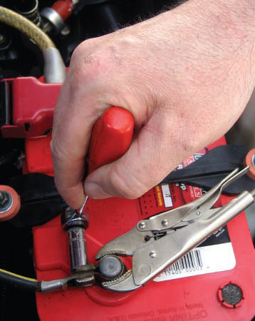
This is the proper way to loosen a battery terminal without allowing it to come loose from the battery post. In this case, I added the ground wire for an automotive security system without disconnecting the battery.

This is the correct way to add this ground wire. Slide the ring terminal under the head of the clamping screw on the side opposite the nut. In this fashion, the battery can be disconnected for any reason without accidentally disconnecting this ground wire from the terminal.
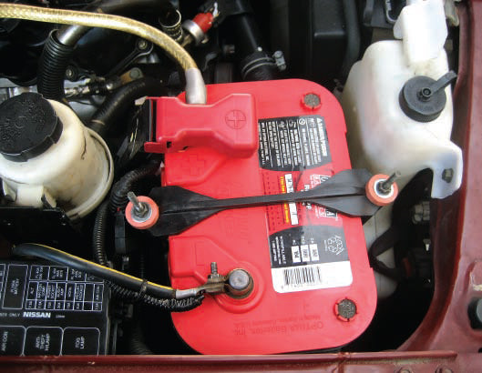
This is the finished connection. Note that this does not interfere in any way with the OEM battery terminals and would allow the battery to be disconnected or even swapped easily.
If you’re working on a newer vehicle laden with computers, disconnecting the battery can have a host of ill side effects. One such example is re-learning the idle. If the procedure outlined by the manufacturer is not followed after the battery is reconnected, the vehicle may not idle or even run correctly. In my years as an electronics installer, there were many cases that we used vise grips to ensure that the battery terminal did not come off when connecting an aftermarket accessory so that we didn’t have to call the dealer in an effort to learn what those procedures were.
I recommend disconnecting the battery when:
- Making major changes or additions to the electrical system.
- Making extensive changes to the vehicle’s drivetrain, exhaust, or suspension components.
- Working around a battery in tight quarters—as I mentioned earlier, the end of a wrench or ratchet between the positive battery terminal and the chassis is a good way to get in trouble fast!
- Tach signal—typically found at the negative side of the coil.
- 12 volts when the ignition switch is in the run position.
- Dash lamp circuit, so that the tach is illuminated when the parking lights are on and its brightness varies with the dimmer control.
- Ground.
This is a good example for leaving the battery connected during its installation.
Installing the Tach
Here is the procedure for safely installing the tach with the battery connected.
Step 1: Be sure the ignition switch is in the off position.
Step 2: Mount the tach.
Step 3: Run the wiring from the tach under the vehicle’s dash.
Step 4: Route the signal lead from the tach through a rubber grommet in the firewall to the coil and connect it to the negative side of the coil. (Note that since the ignition switch is off and the vehicle is not running, neither side of the coil has any voltage present on it.)
Step 5: Route the ignition (+) lead from the tach to a source of + 12 volts when the ignition switch is in the run position. (Note that this lead needs to be fused at the source of power per the tach manufacturer’s specification.)
Step 6: Route the illumination (+)lead from the tach to the dash lamp circuit so that the light within the tach varies with the dimmer circuit, along with the rest of the lights on the vehicle’s dash-board.
Step 7: Connect the ground (-) lead from the tach to chassis ground.
Step 8: Install the fuse in the fuse holder that you connected to the source of ignition (+) in Step 5.
Step 9: Turn the dash lamps on and verify the correct operation of the illumination of the tach by rotating the dimmer to MAX and to MIN.
Step 10: Start the vehicle and verify operation of the tach.
As you can see, at no point during the installation of the tach did we make connections to a live circuit. In the event that we would have pinched or shorted any of the wiring to the tach during the installation, it would have had the same results as if we had done the installation with the battery negative disconnected, then reconnected it after the installation was complete. However, in steps 4, 5, and 6, it is necessary to verify the functionality of the wiring we’re connecting to—this is not possible with the negative battery cable disconnected. Chapter 5 details step by step how to verify the wiring you’re connecting to as you do the install.
DISCLAIMER: Connecting power to any piece of aftermarket electronics, whether to the battery directly or not, should be the last step you do and not the first. To simplify installation and provide an added measure of safety, I prefer to run wiring from the device to the connection point(s) and not the other way around. This power connection should be fused near the connection point to protect the wiring and circuit you’ve tied into. Note that in the previous example, the last step before verifying correct operation of the tach was to install the fuse in the fuse holder that supplied power to the tach. Without the fuse installed, no power can flow to the tach from the ignition circuit, even with the ignition switch in the RUN position.
OK, take a much-deserved deep breath and cue up your favorite car show from the DVR—you’ve just gotten through the most difficult part of this book. It’s all downhill from here!
Written by Tony Candela and Posted with Permission of CarTechBooks
GET A DEAL ON THIS BOOK!
If you liked this article you will LOVE the full book.

