Camshafts Demystified
Camshaft Lobe Separation Angle Matters
When finding the perfect cam for a street engine, Lobe Separation can help do the trick. Could you take two cams that are ground with EXACTLY the same lift and duration and still get one to make more power than the other? Of course, and if you picked the wrong lobe separation angle you might lose power. I think the cam companies do this just to keep us guessing. It’s an area where camshaft design gets very confusing.

Find more tech tips like this in the book: HIGH-PERFORMANCE CAMS & VALVETRAINS: THEORY, TECHNOLOGY, AND SELECTION
Learn everything you need to know about the camshafts by getting your copy here!
SHARE THIS ARTICLE: Please feel free to share this article on Facebook, in forums, or with any clubs your participate in. You can copy and paste this link to share:
LSA and LC
Lobe Separation Angle (LSA) is NOT the same as Lobe Centerlines (LC), although the two are directly connected.
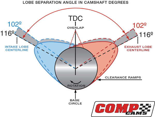
The Lobe Separation Angle is measured as the degrees that the crankshaft rotates BETWEEN the exhaust valve’s maximum lift point (aka: Exhaust Centerline) and the intake valve’s maximum lift point (aka: Intake Centerline). Check the lead illustration in this story from COMP Cams to show this effect. The highest lift points on the lobes are referred to as the cam “Lobe Centerlines” and are usually ground somewhere between 102 and 122 crankshaft degrees. Since Lobe Centerline is referenced in relation to crankshaft degrees as well, it can be moved around, depending on where you install the cam.
When you degree the cam, you’re usually checking to see if it’s installed at the cam manufacturer’s recommended Intake Centerline point. Let’s say your cam manufacturer recommends installing the cam at a 112-degree Intake Centerline. Using the degree wheel you check the intake’s highest lift point to be exactly at 112-degrees. That means you’ve now installed the cam “Straight Up”. If the degree wheel shows an intake max lift point of 110-degrees, the cam is now INSTALLED 2-degrees advanced from the manufacturer’s settings. If the degree wheel showed an installed position of 114-degrees, the cam is now INSTALLED 2-degrees retarded.
Lobe Separation Angle, on the other hand, is ground into the cam and it cannot be changed (see red arc in illustration). To check your LSA you calculate it by adding the intake and exhaust Lobe Centerline figures together and dividing their sum by two (Ex: 112 intake Centerline + 116 exhaust Centerline = 228 / 2 = 114-degree LOBE SEPARATION ANGLE).
There’s more. These are also the figures used to indicate how much the cam’s intake lobe was ground “advanced” or “retarded” from the factory. To find intake lobe advance/retard, simply subtract the Intake Lobe Centerline from the Lobe Separation Angle (i.e.: LSA 114 – IC 112 = 2-degree advance). This difference is how far advanced or retarded your cam was ground at the factory, 2-degrees in our example here. You cannot change Lobe Separation Angle because it is ground at the factory. But you can advance or retard the cam in relation to the crank when it’s degreed-in.
Valve Overlap
Lobe Separation is not the same as valve overlap either. Valve overlap (see small red triangle in middle of illustration) is often ignored, but it is critical to making power. Overlap is the degrees that both intake and exhaust valves are open at the same time. All cams have some amount of overlap and certain engines respond differently to it. A good intake tract will not need as much overlap, while a restricted intake tract would suffer from a cam with too much overlap. When you observe the valve train events at their most basic levels, the closing of the intake valve has the most effect on power. Close it too late and you’ll lose power because the piston will force the incoming fresh intake charge right back out through the carb from an effect known as “Reversion.” Close the intake valve too soon and the cylinders won’t breathe in all that fresh air and fuel. A perfect engine would shut the intake valve precisely as the air/fuel column stops filling the cylinder. However, finding that point is difficult because the entire intake tract, from the air cleaner to the cylinder head, and even the exhaust system all have an effect on it.
Engine vacuum, which is something all our street engines need, is directly controlled by overlap too. Typically, a wider lobe separation angle of 112-116 degrees will mean less overlap and higher vacuum at idle, while a narrower lobe separation (102-108) provides just the opposite. Big race cams may be the exception, because they can have a wide lobe separation angle like 118-degrees and still have lots of overlap and make little vacuum because the intake valve opens very early in the cycle and it stays open long past when the exhaust valve begins to open. That’s what you’re hearing in stout race engines. The intake and exhaust tracts working together give it that wicked tone, particularly at idle.
With street cams, the wider you move the lobe centers apart, such as 116-degrees, the less overlap you typically have. Although both wide (112-116) and narrow (102-110) lobe separation angles do have an effect on overlap, it’s still possible to get a lot of overlap with very wide lobe separation angle cams. It’s the scavenging effect of the high velocity exhaust gases rushing out that pulls the fresh fuel/air charge into the chamber. Why is all this important? It has to do with the cylinder heads, exhaust system, and how well the engine breathes. If you’ve got bad cylinder heads or a weak exhaust system the wrong LSA might not put enough fresh charge into the cylinders.
Separating the Numbers
Several years ago I asked COMP Cams to help me with a very detailed analysis of cam LSA. COMP ground up five street rollers for me with exactly the same lift (.495” intake, .502” exhaust), and the exact same duration (at 0.050”: 235 intake, 240 exhaust), and the exact same advance ground into the intake lobes (+4-degrees), but each one had a different Lobe Separation Angle (LSA). I spent two days on the dyno testing them all in a 10:1cr, 350ci GM Performance Parts crate engine that had been tweaked a little to yield a bit more power. The reason I ran solid roller cams for this test was to eliminate the break-in period flat-tappet cams required between each test. Installed position and valve lash were checked very carefully for each cam so as not to be a factor in the results.
Check out the torque curves for the five cams I tested. See how the 106 and 110 Lobe Separation Angle cams are practically identical. COMP Cams engineers told me that since the engine I tested featured a single-plane intake manifold and open headers without mufflers, it was able to breath fairly well and had no trouble scavenging its cylinders. Consequently, the 106 LSA cam probably over-scavenged the cylinders, which cost some power, and the 110 LSA cam most likely under-scavenged an equal amount so the dyno runs from both of these cams looks almost identical. In between was where the 108 LSA cam performed substantially better in this engine. It’s kinda’ like the Goldilocks and the Three Bears fable. The 106 LSA cam scavenged too much, and the 110 LSA cam couldn’t scavenge enough, but the 108 LSA cam scavenged just right. This conclusion is further supported by the relatively poor performance of the wider 112 and 114 LSA cams. Their weak numbers meant the this engine wanted to breath with some overlap to make its best power. Pay close attention to the average and max power figures because they tell the biggest tale. Another benefit to running a higher LSA cam is a better idle quality with more vacuum, so I’ve listed vacuum at 1,000 rpm with no load on the engine for each cam as well.
Lobe Separation Angle Torque
| LSA | 106 | 108 | 110 | 112 | 114 |
| RPM | TQ | TQ | TQ | TQ | TQ |
| 3600 | 375 | 380 | 379 | 383 | 378 |
| 3800 | 387 | 391 | 388 | 390 | 384 |
| 4000 | 407 | 407 | 403 | 402 | 395 |
| 4200 | 414 | 421 | 414 | 411 | 404 |
| 4400 | 419 | 430 | 423 | 418 | 412 |
| 4600 | 426 | 435* | 426 | 424 | 419 |
| 4800 | 429* | 434 | 427 | 425 | 420 |
| 5000 | 428 | 434 | 428 | 425 | 422 |
| 5200 | 429 | 434 | 431* | 427* | 423* |
| 5400 | 427 | 432 | 430 | 421 | 422 |
| 5600 | 423 | 427 | 424 | 415 | 416 |
| 5800 | 414 | 419 | 415 | 404 | 407 |
| 6000 | 404 | 410 | 405 | 393 | 395 |
| 6200 | 395 | 400 | 395 | 381 | 384 |
| 6400 | 383 | 389 | 383 | 367 | 370 |
| Avg | 411 | 416 | 411 | 406 | 403 |
| Max | 429 | 435 | 431 | 427 | 423 |
| Vac | 10.2" | 11.9" | 13.1" | 14.5" | 14.9" |
*Note how the narrower (numerically lower) LSAs made peak torque 400 to 600 rpm lower than the higher LSA cams. However, in all tests, horsepower peaked at almost the same RPM (between 6,200 and 6,400 rpm) for every cam. Most engines will respond similarly to increased overlap from a narrow LSA cam.


Next in the path is the intake port. This 220cc Dart port is a good candidate for lots of power when combined with the right camshaft.

The cylinder head’s chamber also depends heavily on camshaft LSA to help achieve maximum filling capacity. A weak chamber might need a radically different cam than a good chamber would.

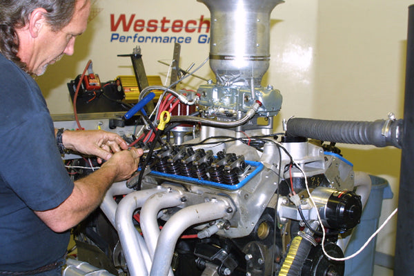
To swap five different cams in a short two days on the dyno I utilized a COMP Cams belt drive unit. This also gave me the ability to fine-tune each cam’s installed position for ultimate accuracy.

You can see that after removing the timing pointer and cam gear, the cam slides out of the engine without having to pull off the harmonic dampener. This really saves time.

Each cam was carefully lashed to the exact same specs.

Once the lash was set, each cam was checked to be installed at the correct Intake valve opening point at 0.050” lift. Note dial indicator on top of pushrod.

With the Tavia timing pointer reattached we checked to see where the intake valve opened.

Six-degrees before Top Dead Center is what the cam’s spec card called for the “Intake opening at 0.050” for each cam. The ATI dampener really helped out checking this important step.

Since not all cams can be ground exactly the same, we used the belt drive to further equalize the installed position of every cam for each test.

Sources
ATI Performance Products
6747 White Stone Rd.
Baltimore, MD 21207
(410) 298-4343
www.atiperformanceproducts.com
COMP Cams
3406 Democrat Rd.
Memphis, TN 38118
(901) 795-2400
www.compcams.com
Dart Machinery
353 Oliver St.
Troy, MI 48084
(248) 362-1188
www.dartheads.com
Tavia Performance Products, Inc.
3249 Oleander Ave
Ft. Pierce, FL 34982
(800) 281-0767
(772) 461-4690
www.tavia.com
Westech Performance Group (dyno)
11098 Venture Dr., Suite C
Mira Loma, CA 91752
(951) 685-4767
www.westechperformance.com
Written by Mike Petralia and posted with permission of CarTech Books
If you liked this article, you will LOVE this book!
Get your copy here.


